Pi-powered central heating phase 1
Not that long ago I wrote about planning to set up a basic Raspberry Pi-controlled central heating system. A few components later, and the relatively simple proof of concept is complete. This post is a summary of what I’ve done and learned, in case I forget it all next week.
Firstly, a disclaimer
Okay, so it’s obvious but I have to say it: messing around with mains electricity is dangerous and you could end up getting a pretty big shock (literally). If you don’t know what you’re doing and don’t fancy killing yourself (and potentially other people), get someone else to do it! Everything here is provided without any kind of assurance that it will work for you. Basically, don’t blame me if you do something that gets someone electrocuted or causes your house to burn down. You have been warned (I do enjoy a bit of melodrama)!
The set up

The use case for our automatic heating system is a little different to normal. We have the pleasure of having 4 LPG bottles fuelling a Worcester 24CDi combi-boiler. This is controlled by a thermostat mounted in the hallway by the front door as well as a simple programmer located just by the boiler.

LPG bottles, the bane of a warm house
The programmer is in-line with the main power supply to the boiler, so outside of the programmed heating times there is also no hot water. The thermostat (thankfully) just controls the heating.
Aims
The flaws in the original setup are pretty obvious, but it’s always good to write down what you’re trying to achieve (otherwise how will you know you’ve succeeded?), so for phase 1 my aims were:
- Heating control which doesn’t affect the hot water supply
- Simple configurable programs for different heating times on different days using cron
- A web interface to switch the heating on and off (for Jennifer)
As we’re entering winter and it’s pretty cold at the moment we don’t actually need a thermostat. Living in a stone house has (for us) meant that we could run the heating permanently and still not feel compelled to remove our jumpers. I also want to tie the logic of switching the heating on and off into a more intelligent system than just using the current temperature, so it’s a job for phase 2.
Hacking into the central heating system
There are a number of ways to break into the central heating system. Because the boiler also services the hot water system I didn’t want to just switch the entire unit on/off, so had to use the thermostat interface of the boiler. There is a handy wireless thermostat fascia for most Worcester boilers, and if you’re lucky enough to have one of those you can fairly simply spoof it, which is a much less invasive way to get into the system.
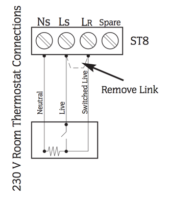
The boiler has a 230V room thermostat connection. I wanted to keep that in the system as a fail-safe. If the clever system dies or becomes self-aware and tries to take over the world we don’t want the pipes to freeze (that would be expensive). Keeping the existing thermostat wired in parallel and turned down to ~5°C means that if it gets that cold the heating will come on regardless. Well, assuming we haven’t run out of gas (again) at least.
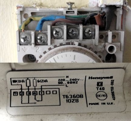
The thermostat is the logical point to tap into the circuit. It has screw-terminals for easier installation and the thermostat is closer to my ideal mounting location than the boiler. Ours is a pretty standard (and old) Honeywell thermostat (see pictures below). Inside the thermostat is a handy wiring diagram showing the boiler uses 4 connections:
- Live
- Switched live
- Neutral
- Earth (not really a boiler connection, but necessary)
Closing the switch on the thermostat bridges live and switched live. Just because I’m paranoid, I double-checked this with a multimeter before adding anything to the system. Rather than building a complete parallel system, I opted to insert a relay to manually close the circuit between live and switched live, but not yet!
Proof of concept: simple Pi control
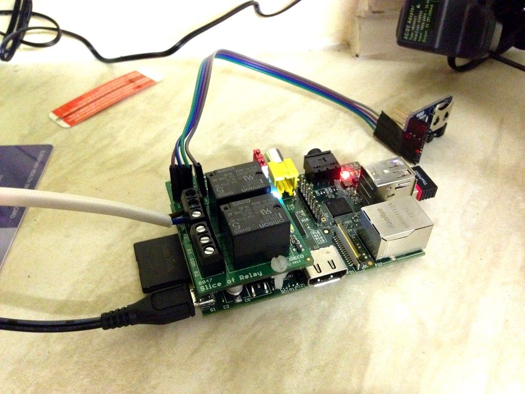
Before plugging into the live system, I wanted to prove the system would work in isolation. The components needed are:
- A Raspberry Pi (I’m using an early rev A Pi, not that it makes any difference) + power supply + SD card @ ~£40 total
- A Pi Hut wireless dongle (http://thepihut.com/products/usb-wifi-adapter-for-the-raspberry-pi) @ £8
- A Ciseco “slice of relay” board (http://shop.ciseco.co.uk/slice-of-relay/) @ £10
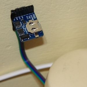
- A Ciseco POD RTC/EEPROM/Temp (http://shop.ciseco.co.uk/i-o-pod-rtc-eeprom-temp/) @ £11
- 3m 5A cable
If you’ve got a Pi sitting around doing nothing it’s a pretty cheap project.
When my components turned up (Ciseco get points for a very fast turnaround) I needed to solder the RTC/temperature sensor cable into the relay board. If you’re doing this “properly” you want to get hold of a 2x13 header pin and solder that onto the expansion holes in the slice of relay, but I was feeling cheap and wanting to get everything up and running.
The relay board uses GPIO pins 24 & 25 (as well as the 5V & ground pins). The RTC/temperature sensor runs on 3V3 and ground pins as well as the SDA and SCL pins for i2c communication, so can be safely added on top of the relay.
Later this week I’ll be adding the RFM12B Pi expansion board, which will take a bit of rejigging. I’ll post photos once it’s working.
Software
Because this unit is likely to suffer from power outages (amusingly we had one just 10 minutes before writing this sentence) I’ve opted to use the Industrial Perennial Environment. It also happened that there’s an emoncms gateway project using IPE (see here for more information).
As my intention is to run emoncms to capture historical data from the system as well as from a bunch of environmental and energy sensors, I used the pre-built “rock solid gateway” image as my base.
When you’re working with IPE, you just need the commands ipe-ro and ipe-rw, which remount the disk in (unsurprisingly) R/O and R/W mode respectively. Just don’t forget to switch it back once you’re finished editing.
I’m assuming the Pi could die at any time, so I don’t keep anything on it I’ve not got stored somewhere else. A simple way to achieve this is to create a Github repository for the directory you’re adding scripts to, but be a little careful about exposing private passwords and API keys to the world. The scripts below are in a repository here.
To get the Pi into a working state from the base SD card image I did the following:
- Login with root/root
- Resize the partition to fill the SD card:
$ firstboot - Run firstboot again to set the root password (among other things):
$ firstboot
The next step is to get the networking up and running. I wanted a static IP address of 192.168.0.222 on the wired interface just in case I need to get into it manually. I need the PiHut Wifi dongle to DHCP onto our secure(ish) network (don’t forget to ipe-rw first!):
auto lo

iface lo inet loopback
iface eth0 inet static
	address 192.168.0.222
	netmask 255.255.255.0
	gateway 192.168.0.1
	broadcast 192.168.0.1
	dns-nameservers 192.168.0.1

allow-hotplug wlan0
auto wlan0
iface wlan0 inet dhcp
	wpa-ssid "myhomenetwork"
	wpa-psk "mysharedkey"
	gateway 192.168.0.1
You’ll probably want to tweak the above so your network group/router is right, and add your WPA SSID and pre-shared key.
A quick reboot should see the device appear on the wireless network.
The next step is to do an update of the OS and put some key packages on:
$ apt-get update
$ apt-get install vim dnsutils git
$ apt-get dist-upgrade
$ apt-get autoremove
Finally let’s reboot
$ sync
$ reboot
Sensor reading & control with GPIO, i2c and WiringPi
To enable support for i2c we need to enable the kernel modules for i2c. In /etc/modprobe.d/raspi-blacklist.conf add a # to comment out the i2c module so it looks like this:
#blacklist i2c-bcm2708
Then add the following modules to /etc/modules:
i2c-bcm2708
i2c-dev
I also installed the handy i2c-tools:
sudo apt-get install i2c-tools
To make use of the GPIO pins on the Raspberry Pi we’ll need the excellent WiringPi library.
git clone git://git.drogon.net/wiringPi
cd wiringPi
sudo ./build
My scripts are being written in Python, so we’ll grab the wrapper for that too:
sudo apt-get install python-setuptools python-dev
git clone https://github.com/Gadgetoid/WiringPi2-Python.git
cd WiringPi2-Python
sudo python setup.py install
We also need to install the Python smbus module for i2c support:
sudo apt-get install python-smbus
After a quick reboot you can test the gpio utility and see the GPIO status:
root@oemgateway:~# gpio readall
+----------+-Rev1-+------+--------+------+-------+
| wiringPi | GPIO | Phys | Name   | Mode | Value |
+----------+------+------+--------+------+-------+
|      0   |  17  |  11  | GPIO 0 | IN   | Low   |
|      1   |  18  |  12  | GPIO 1 | IN   | Low   |
|      2   |  21  |  13  | GPIO 2 | IN   | Low   |
|      3   |  22  |  15  | GPIO 3 | IN   | Low   |
|      4   |  23  |  16  | GPIO 4 | IN   | Low   |
|      5   |  24  |  18  | GPIO 5 | OUT  | Low   |
|      6   |  25  |  22  | GPIO 6 | IN   | Low   |
|      7   |   4  |   7  | GPIO 7 | IN   | Low   |
|      8   |   0  |   3  | SDA    | ALT0 | High  |
|      9   |   1  |   5  | SCL    | ALT0 | High  |
|     10   |   8  |  24  | CE0    | ALT0 | High  |
|     11   |   7  |  26  | CE1    | ALT0 | High  |
|     12   |  10  |  19  | MOSI   | ALT0 | Low   |
|     13   |   9  |  21  | MISO   | ALT0 | Low   |
|     14   |  11  |  23  | SCLK   | ALT0 | Low   |
|     15   |  14  |   8  | TxD    | ALT0 | High  |
|     16   |  15  |  10  | RxD    | ALT0 | High  |
+----------+------+------+--------+------+-------+
You can also verify the i2c bus is operational by using i2cdetect -y 0 for revA Pi units or i2cdetect -y 1 for newer revB units.
Then we’re ready to have a bit of fun.
Control and report
The Slice of relay uses standard GPIO:
- Pin 24 for relay A
- Pin 25 for relay B
Some useful addresses for the POD RTC/EEPROM/TEMP board:
- Real Time Clock (BQ32000 from TI) I2C address is 0x68
- Temperature sensor (TMP100NA from TI) I2C address is 0x48
- 32Kb EEPROM (24LC256) I2C address is 0x50
For the following I created a Github repository which may provide a good starting point.
Setting up the Real Time Clock
First of all you’ll need to add the RTC kernel module rtc-ds1307to /etc/modules. You can activate it without having to reboot:
sudo modprobe rtc-ds1307
Assuming the system time is correct (note: check it!) we then want to load add the device and set it to match the system time:
echo ds1307 0x68 > /sys/class/i2c-adapter/i2c-0/new_device
hwclock -w
To load the device on reboot and update system time from the RTC add the following to /etc/rc.local (you’ll want to run it once manually as well):
echo ds1307 0x68 > /sys/class/i2c-adapter/i2c-0/new_device
hwclock -s
Logging the temperature to emoncms
The first step is to read the temperature from the TMP100NA (see https://github.com/spikeheap/pi-switch-post/blob/master/readTemp.py):
import smbus
import time

bus = smbus.SMBus(0)
data = bus.read_i2c_block_data(0x48, 0)
msb = data[0]
lsb = data[1]
# Print degrees Celsius (I have no idea where I got 0.0625 from...)
print (((msb << 8) | lsb) >> 4) * 0.0625
To get the temperature logged to emoncms we just need to get the results from the script and lob it at the REST API see the source:
curl "http://emoncms.org/api/post?apikey=YOURAPIKEYHERE&json={piTemp:`python /root/pi-switch-post/readTemp.py`}"
Getting some heat
Controlling the relay is pretty straightforward, and we just need to take the pin (24 for A) high or low, as needed:
wiringpi.pinMode(24,1)

initialState = wiringpi.digitalRead(24)
wiringpi.digitalWrite(24, 1) #replace 1 for 0 to switch it off
currentState = wiringpi.digitalRead(24)
See the source code for a more complete example.
Extended testing
What’s the point in building a computer-controlled heating system if you have to turn it on and off yourself? Before I get into ‘intelligent’ heating control I want to run the system for a couple of weeks to prove it works. This can be easily accomplished by editing your crontab (crontab -e):
# Update the time from the RTC hourly
0 * * * * hwclock -s

# Post sensor readings to emoncms
* * * * * /root/ryan_scripts/tempToEmon.sh > /dev/null
* * * * * /root/ryan_scripts/heatingStateToEmon.sh > /dev/null

# Every morning, 6:30 to 7:00
30 6 * * * /root/ryan_scripts/switchHeatingOn.sh > /dev/null
0 7 * * * /root/ryan_scripts/switchHeatingOff.sh > /dev/null

# Mon, Fri 6pm to 7pm
0 18 * * 1,5 /root/ryan_scripts/switchHeatingOn.sh > /dev/null
0 19 * * 1,5 /root/ryan_scripts/switchHeatingOff.sh > /dev/null

# Tues, Weds, Thur 22:20 to 23:00
20 22 * * 2,3,4 /root/ryan_scripts/switchHeatingOn.sh > /dev/null
0 23 * * 2,3,4 /root/ryan_scripts/switchHeatingOff.sh > /dev/null
And there we have it, a basic central heating control system, but with the potential for so much more. Obviously the scripts above are pretty rough around the edges, but as a proof of concept I’m pretty happy with it.
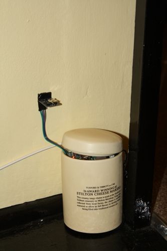
In the photo above I rested the temperature sensor against the wall. Don’t do that normally if you want accurate readings!
I realise I haven’t covered the basic web interface yet. I have done it, honest, but this post is already a little long so I’ll talk about that separately.
Next steps
- A pretty front-end
- Intelligent control of the controllers based on sensor state
- Integration with emoncms for historical data tracking and analysis
But for now I’m going to light a fire and forget about gas for a bit :).
References & resources
The following were useful to me, and may be useful to you:
- IPE + emoncms http://harizanov.com/2013/08/rock-solid-rfm2pi-gateway-solution/
- IPE Raspbian http://nutcom.hu/?page_id=108
- WiringPi library: https://projects.drogon.net/raspberry-pi/wiringpi/download-and-install/
- https://projects.drogon.net/raspberry-pi/wiringpi/pins/
- http://learn.adafruit.com/adding-a-real-time-clock-to-raspberry-pi/wiring-the-rtc
- http://www.ti.com/product/tmp100#topsidemarking
- http://bradsmc.blogspot.co.uk/2013/04/reading-temperature-from-tmp02.html
- Build emoncms http://emoncms.org/site/docs/raspberrypibuild http://emoncms.org/site/docs/installlinux
- Pi python wiring https://github.com/Gadgetoid/WiringPi2-Python
- Ciseco slice of relay demo: https://github.com/CisecoPlc/B047-Slice-of-Relay
NodeJS Raspberry Pi resources
I initially wanted to use NodeJS, so I’ve left those links in just in case I come back to it later.
- Setting up nodejs on Raspberry Pi http://blog.rueedlinger.ch/2013/03/raspberry-pi-and-nodejs-basic-setup/
- Bootstrap on Express http://www.andreagrandi.it/2013/02/24/using-twitter-bootstrap-with-node-js-express-and-jade/
- Intro to Express http://evanhahn.com/understanding-express-js/
- Node WiringPi https://npmjs.org/package/node-wiringpi
- Node v0.10.22 on pi http://thethingsystem.com/dev/Bootstrapping-the-Raspberry-Pi.html